
Introduction to Hardware Triggering Concepts
Hardware triggering is a fundamental technique in scientific imaging that
enables direct electronic communication between hardware components. By
bypassing the computer and its associated software overhead, hardware
triggering achieves response times that would be impossible through
conventional software control. This article provides a comprehensive overview
of the principles, terminology, and practical applications of hardware triggering,
with particular attention to the needs of researchers working with CMOS
cameras, where the rolling shutter in camera designs is a key consideration.
The Purpose and Benefits of Hardware Triggering
The primary purpose of hardware triggering is to facilitate communication
between hardware components with the absolute minimum possible latency. In
practice, this means response times measured in microseconds or less. While
modern computers are remarkably fast in many respects, the round-trip
journey of a signal through the computer’s processing pipeline introduces
delays that are both significant and variable. These delays depend on the
computer’s current workload, making software-based timing unreliable for
applications that demand microsecond precision.
| Application Scenario | Why Hardware Triggering Is Preferred |
| Synchronizing LED or laser with camera exposure | Requires microsecond response times |
| Coordinating camera acquisition with stage or filter wheel movement | Ensures frames are captured only after movement is complete |
| Controlling acquisition timing relative to external experimental events | Provides absolute precision and reproducibility |
| Managing exposure time from external hardware | Enables precise timing control independent of software |
| Synchronizing multiple cameras | Ensures simultaneous acquisition across all devices |
| Achieving pseudo-global operation with rolling shutter | Enables effective global shutter emulation |
How Hardware Triggering Works in Practice
The exact implementation of hardware triggering varies between
manufacturers, and it is always advisable to consult the specific instructions
provided with each piece of equipment. Nevertheless, the general principles
are broadly consistent across different systems.
To use hardware triggering, a component must be equipped with one or more
trigger ports. These ports serve as the physical interface through which trigger
signals are transmitted and received. Trigger cables are connected between
components, creating a direct electrical pathway for signal transmission.
Once the physical connections are established, software is typically used to configure how each component should interpret the triggers it receives.
For scientific cameras, the process of enabling hardware triggering usually
involves instructing the camera in software to await external triggers, rather
than operating on its own internal timing. In this triggering mode, the
acquisition is set up and started as usual, but rather than beginning
immediately, the camera enters a waiting state. It remains in this state until it
receives an external trigger signal, at which point it begins acquiring images.
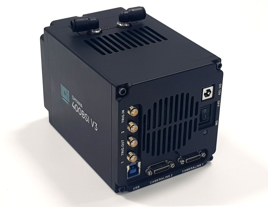
The rolling shutter behavior of CMOS cameras makes them particularly
dependent on well-coordinated triggering, especially when used with external
light sources. This dependency is why many rolling shutter cameras offer
extensive trigger input and output capabilities, and the Tucsen Dhyana 400BSI
v3 is a good example of a camera designed with these needs in mind.
Understanding the rolling shutter in camera systems is crucial for researchers
who need to synchronize their imaging with external experimental events.
Trigger Outputs from Cameras
Most cameras are also capable of generating trigger outputs, which inform
other hardware about the camera’s current state. Common output signals
indicate whether the camera is currently exposing, whether it is not exposing,
or whether all rows of the sensor are simultaneously exposing—a feature
particularly relevant for pseudo-global shutter applications. Some cameras use
multiple pins or breakout cable outputs, with each pin indicating a different
aspect of the camera’s state. Other cameras feature programmable pins that
can be configured in software to output any desired function.
The specific trigger output capabilities vary between camera models. For
instance, the Tucsen Dhyana 400BSI v3 offers a range of trigger output options
that can be tailored to different experimental requirements. By selecting the
appropriate output configuration, researchers can synchronize their camera
with a wide variety of external hardware components, including light sources,
stages, and filter wheels. The rolling shutter in camera systems often
determines what types of trigger outputs are available and how they can be
configured.
Advanced Triggering Setups and Controllers
For advanced imaging setups that require sequential movement and
coordinated control of multiple hardware components, a dedicated triggering
controller is often employed. These controllers are commonly referred to as
Data Acquisition (DAQ) cards. A DAQ card is typically connected to the
computer and programmed with instructions via software. Once programmed,
however, the DAQ card operates with significantly higher timing precision and
lower latency than software-based control, as it does not need to wait for the
computer’s operating system to process each instruction.
For setups that require less stringent timing precision, alternative controllers
such as Arduino or similar hobbyist-grade programmable electronic
components can be used. These offer a more affordable entry point into
hardware triggering, though they may not achieve the same level of timing
accuracy as dedicated DAQ cards. When designing complex multi-component
systems, researchers must carefully consider how the rolling shutter in camera
systems will interact with their triggering controllers.
Summary of Hardware Triggering Fundamentals
| Topic | Key Points |
| Definition | Direct signal transmission between hardware components |
| Primary Benefit | Microsecond latency and consistent timing |
| Required Components | Trigger ports, cables, and compatible hardware |
| Camera Trigger Input | Camera waits for external signal to begin acquisition |
| Camera Trigger Output | Camera sends state information (exposing, ready, etc.) to other hardware |
| Advanced Control | DAQ cards or Arduino for multi-component coordination |